Contents | Index | < Browse | Browse >
A3000 Power Supply
240V/120V Conversion
Commodore shipped the A3000 with a fixed input voltage power supply to suit the destination country.
The 135W power supply units were especially produced by Taiwanese company Liton for Commodore; these
supplies are unique to the A3000 and are not physically compatible with other models.
Standard A3000 power supply models are:
- 240V = Liton model PE-5161-1 (C= part no. 390500-01)
- 120V = Liton model PB-5161-1 (C= part no. 390500-02)
Unlike many modern switch mode power supplies, the input voltage is fixed according to the power
supply model. There is no switch to manually select the input voltage so a step up/down transformer
is required if using the A3000 power supply with a different AC mains input voltage.
Internally the Liton models PE-5161-1 and PB-5161-1 share the same printed circuit board and a minor
difference in the board population.
The following information is provided by Gennaro Montedoro (gennyflick) on changing the Liton A3000
power supply input voltage to eliminate the need for a step up/down transformer. All text written
by Anthony Hoffman.
WARNING!
The following information involves working with equipment operating
at lethal voltages. Do not attempt opening or modifying the power
supply unless you are fully experienced and confident working around
AC mains voltages.
|
-
Remove the top cover of the A3000; there are four screws around the
case sides and a single screw rear top centre. The case slides forward off the
chassis.
-
Unplug the DC connectors from the main board, floppy drive(s) and
hard drives(s).
-
Remove the power supply from the A3000 chassis; there are three
screws around the outside edge and a single screw on the rear of the chassis
above the AC supply connector to remove; the power supply will then lift out of
the chassis.
-
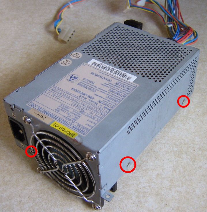
Open the power supply case by removing the three screws highlighted
in the image below. Older variants of the power supply have additional screws in
different locations than shown below.
-
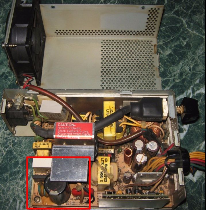
Hinge open the power supply cover and locate the area of the board
containing the two 470uF 200V reservoir capacitors as highlighted below.
-
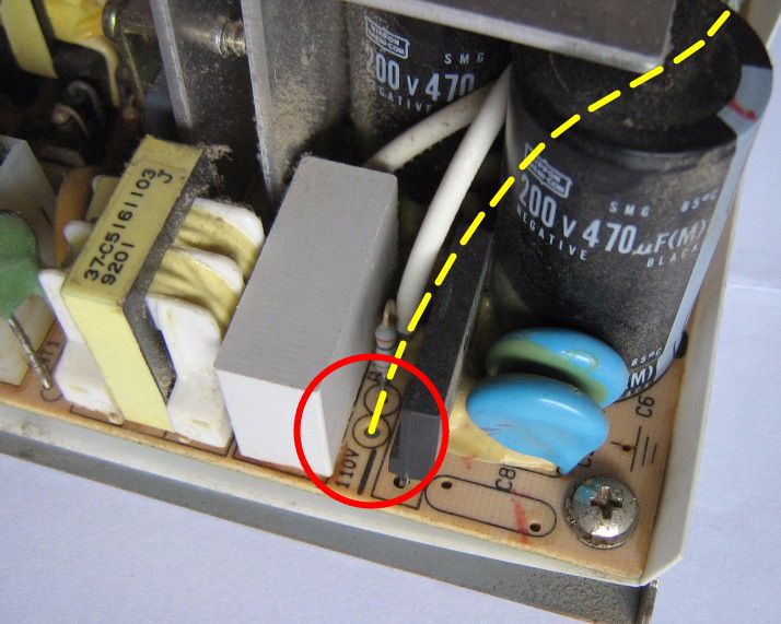
To convert FROM a 120V model TO a 240V model, the single wire between
the reservoir capacitors and the "110V" pad must be removed. First locate the 110V
pad beside bridge rectifier as shown below. Un-solder or cut the wire off at the top
side of the circuit board.
It is also advisable to replace varistor RV21 (located between AC input connector SW1
and inductor L3) with a 275V AC rated part as the original part may be a lower working
voltage that is only suitable for 110V operation. A suitable replacement for RV21 is
element14 part number 1057202.
-
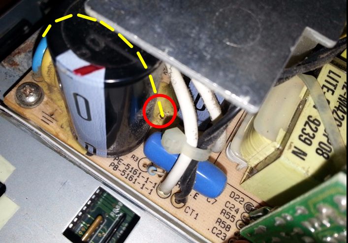
Locate the other end of the wire which connects to the board between the two
reservoir capacitors as shown below. Un-solder or cut the wire off at the top side of the
circuit board.
-
To convert FROM a 240V model TO a 120V model, a single wire between
the reservoir capacitors and the "110V" pad must be installed. This is the reverse of the
above two steps, which also requires removing the circuit board from the chassis to access the two
solder pads on the bottom side of the board. The top side of the board between the capacitors
will have shake-proof glue between the capacitors which must be removed to access the hole in
the board to fit the linking wire.
-
Reverse the disassembly steps to reassemble the power supply and reinstall into
the A3000 chassis. Do not fit the A3000 top cover yet.
-
IMPORTANT: Using a permanent marker pen, cross out the original input
voltage on both the label on the rear of the computer chassis and both references on top
of the power supply and clearly write the new input voltage. Or use a label printer to relabel
the new input voltage. This will prevent someone later connecting the computer to the
incorrect mains voltage which will damage the power supply.
-
Set jumper J200 according to your AC mains frequency.
The jumper is located on the A3000 main board beside Fat Agnus in approximately the centre of
the expansion slot area. For a 50Hz supply the jumper should be set to PAL. For a 60Hz supply
the jumper should be set to NTSC.
-
Check the main board power connector is plugged in as well as the hard
drive/floppy drive power. Connect the AC mains cable to the power supply and check that
the computer powers up normally. Confirm the power supply fan is operating as you may
have disconnected it during the modification.
-
Assemble the A3000 top cover and fasten with the five screws.
Common faults and repairs
WARNING!
The following information involves working with equipment operating
at lethal voltages. Do not attempt opening or repairing the power
supply unless you are fully experienced and confident working around
AC mains voltages.
|
Please note that this information is provided for technicians already familiar with
basic switch mode power supply operation.
This applies to Liton power supply model numbers PE-5161-1 (240V) and PB-5161-1 (120V),
download Schematic here.
Check the incoming mains fuse (5A). If fuse is blown, this is often caused by the high
voltage switching transistors, Q1/Q2 going short circuit. These can be replaced with commonly
available MJE13007G high voltage NPN bipolar transistors, element14 part number
955-7857.
Note that both transistors should always be replaced as a pair. Both Q1 and Q2 are the
same transistor type.
Blowing fuses can also be caused by a short circuit diode in the incoming mains bridge
rectifier, which can be quickly and easily measured for short circuits without unsoldering
from the PCB. Note that the fault current caused by a Q1/Q2 short circuit places excess
stress on the bridge rectifier which can cause it to fail at the same time as Q1/Q2, or
soon after the transistors are replaced. Therefore it is recommended to replace the bridge
rectifier at the same time. A suitable replacement for the original D3SBA60 rectifier is
4GBJ1506F, available from element14 as part number
2750886.
If the mains input fuse is OK, check that approx. 325VDC for the 240V model (approx. 170VDC
for 120V model) is present on reservoir capacitors and that Q1 and Q2 test OK using standard
diode test techniques for BJTs. A common problem is resistors R5 and R8 (2.2 Ohm, 1/4W)
going open circuit. These are positioned either side of Q1 and Q2. Note that R5 is insulated
under a vertical tube of black heat shrink.
In case of a fault that causes the input fuse F1 to blow, this can sometimes damage
thermistor RT1, which is responsible for limiting inrush current at inital power on.
A suitable replacement for RT1 is element14 part number 1688798.
Varistor RV21 protects the power supply from excessive input voltages by causing a fault
current to flow that causes the input fuse F1 to blow. This usually results in
permanent damage to RV21, sometimes failing as a short circuit. A suitable replacement
for RV21 is element14 part number 1057202.
A3000D Power Supply Pinouts
Power Connector (Hard Disk)
Looking At Back Of Plug

     ________________________________
    /                                \
   /    __      __      __      __    \
  |    /  \    /  \    /  \    /  \    |
  |   | 1Y |  | 2B |  | 3B |  | 4O |   |
  |    \__/    \__/    \__/    \__/    |
  |                                    |
  |_________________________   ________|
                            | |
                            |_|


      Pin 1:  Yellow       +5V
      Pin 2:  Blue         Ground
      Pin 3:  Blue         Ground
      Pin 4:  Orange       +12V

     ________________________________
    /                                \
   /    __      __      __      __    \
  |    /  \    /  \    /  \    /  \    |
  |   | +5 |  |GND |  |GND |  |+12 |   |
  |    \__/    \__/    \__/    \__/    |
  |                                    |
  |_________________________   ________|
                            | |
                            |_|


Power Connector (Floppy)
Looking At Back Of Plug

    _                 _____                 _
   | |               |     |               | |
   | |_______________|     |_______________| |
   |                                         |
   |     ____     ____     ____     ____     |
   |    |    |   |    |   |    |   |    |    |
   |    | 1Y |   | 2B |   | 3B |   | 4O |    |
   |    |____|   |____|   |____|   |____|    |
   |                                         |
   |__________   ____________________________|
              | |
              |_|

          Pin 1:  Yellow       +5V
          Pin 2:  Blue         Ground
          Pin 3:  Blue         Ground
          Pin 4:  Orange       +12V

    _                 _____                 _
   | |               |     |               | |
   | |_______________|     |_______________| |
   |                                         |
   |     ____     ____     ____     ____     |
   |    |    |   |    |   |    |   |    |    |
   |    | +5 |   |GND |   |GND |   |+12 |    |
   |    |____|   |____|   |____|   |____|    |
   |                                         |
   |__________   ____________________________|
              | |
              |_|


Power Connector (Fan)
Looking Straight Into Plug


   #############
   #           #
   #  o     o  #
   #           #
   ##___###___##
      ^     ^
      |     |__Blue    Ground
      |
      |________Red     +12V/0.13A

The fan will not run if these two wires are swapped.


Power Connector (main board)
Looking At Back Of Plug

                     ________
                    |  CLIP  |
 ___________________|________|___________________
|                                                |
|    ____     ____     ____     ____     ____    |
|   |    |   |    |   |    |   |    |   |    |   |
|   | 1Y |   | 2Y |   | 3Y |   | 4Y |   | 5P |   |
|   |____|   |____|    \__/    |____|   |____|   |
|                                                |
|    ___      ____     ____     ___      ____    |
|   |   \    |    |   |    |   |   \    |    |   |
|   | 6B |   | 7B |   | 8B |   | 9B |   |10B |   |
|   |___/    |____|   |____|   |___/    |____|   |
|                                                |
|    ____     ____      __      ____     ____    |
|   |    |   |    |    /  \    |    |   |    |   |
|   |11O |   |12R |   |13Br|   |14G |   |15W |   |
|   |____|   |____|   |____|   |____|   |____|   |
|                                                |
|________________________________________________|


         Pin 1:   Yellow      +5V
         Pin 2:   Yellow      +5V
         Pin 3:   Yellow      +5V
         Pin 4:   Yellow      +5V
         Pin 5:   Purple      +5V Video

         Pin 6:   Blue        Ground
         Pin 7:   Blue        Ground
         Pin 8:   Blue        Ground
         Pin 9:   Blue        Ground
         Pin 10:  Blue        Ground

         Pin 11:  Orange      +12V
         Pin 12:  Red         -12V
         Pin 13:  Brown       TIC
         Pin 14:  Green       +5V User
         Pin 15:  White       -5V

                     ________
                    |  CLIP  |
 ___________________|________|___________________
|                                                |
|    ____     ____     ____     ____     ____    |
|   |    |   |    |   |    |   |    |   |    |   |
|   | +5 |   | +5 |   | +5 |   | +5 |   | +5 |   |
|   |____|   |____|    \__/    |____|   |____|   |
|                                                |
|    ___      ____     ____     ___      ____    |
|   |   \    |    |   |    |   |   \    |    |   |
|   |GND |   |GND |   |GND |   |GND |   |GND |   |
|   |___/    |____|   |____|   |___/    |____|   |
|                                                |
|    ____     ____      __      ____     ____    |
|   |    |   |    |    /  \    |    |   |    |   |
|   |+12 |   |-12 |   |TIC |   | +5 |   | -5 |   |
|   |____|   |____|   |____|   |____|   |____|   |
|                                                |
|________________________________________________|